20
MARINE TECHNICIAN TODAY
|
WINTER 2014
OEM marine fuel injection, as standard
production, began in 1993 with the 502
Magnum MPI from MerCruiser. It was rated at 415
prop-shaft HP with a peak torque of 465 FT LBS at 3,600
to 3,800 RPM. It was a multiport design with a John Lingenfelter
intake system, the intake manifold had bronze water passages to aid
against corrosion. It used 8 Keihin fuel injectors mounted in the lower
intake manifold. MerCruiser designed the throttle body which had two
60mm throttle body bores with stainless steel shafts and ball bearings.
The fuel system had a vapor separator tank (VST) with a high pressure
electric fuel pump inside. There was no fuel cooling offered on this system
as it was designed to keep the VST pressurized to prevent fuel vapor from
forming in the injection system. This first MerCruiser design did not fair
very well against vapor lock, especially in the hot summer months. Also
this engine had a mechanical fuel lift pump installed on the front section
of the seawater pump. The ECM was the MEFI 1 controller and used the
Delco EST ignition system.
About the same time the aftermarket began offering conversion kits
to replace engines with carburetors with EFI. Holley offered a complete
coast guard approved TBI system. In 1994, Cutler introduced a complete
marine MPI fuel injection system called Hyperflow. It was way ahead if
it’s time for a marine EFI conversion. It offered a unique intake manifold
that unlike carbureted manifolds, was designed to flow only more air, not
an air/fuel mixture. This 1000 CFM Hyperflow system enhanced laminar
(think streamlined) air flow to the injectors. Cutler claimed this feature was
better than the turbulent flow created in the intake manifolds designed
for carburetors. Cutler Hyperflow fuel injection offered a billet machined
throttle body. Eight fuel injectors were mounted in 2 long fuel rails on the
top side of the intake manifold, 4 on each side. The multi-port (MPI) system
included the wiring harness, sensors, fuel pressure regulator, electric fuel
pump, fuel filter, and all installation fittings. The engine controller (ECM)
called Powerpoint was self-programming and had the ability to create a
custom EFI fuel map according to engine running parameters. The ECM
was mounted on the starboard side of the throttle body. This was an
all one system built to simply bolt on. The system was purchased from
Cutler by Holley in 1998 and became the most popular aftermarket marine
EFI system.
Throughout the years, Holley and others have truly refined their EFI
systems.Most EFI systemscansupport up to650HP for a typical consumer,
and the high performance systems are capable of supporting the air and
fuel needs of up to1200 HP engines. Most of the complete aftermarket
EFI systems continue to be self-learning but now have incorporated
features that allow you to fine tune the engine for more aggressive running
characteristics or compensate for performance modifications. Installing
these systems on old tech EFI marine engines is becoming more popular.
Depending on which system is used, it can be much cheaper than updating
the engine with the current OEM systems, plus you get the tune-ability
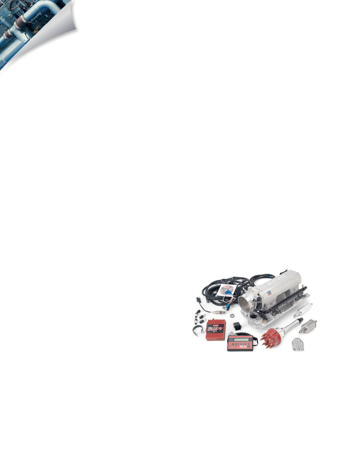
feature. Some of the current manufactures of EFI systems include the
aforementioned Holley, plus FAST, MSD Atomic, Edelbrock Pro-Flo, Rons,
Accel, Kinsler, Quick Fuel Technology and Professional Products.
Marine performance shops seem to favor the Holley Multi Port EFI
systems. Holley’s ECM is fully potted and is certified to ISO 8846, SAE
J1171, is Coast Guard approved for ignition protection and fire resistance,
and can be mounted in any compartment. The fuel injectors and fuel
pumps are not included with the kit but can be purchased separately from
Holley. The reason for this is the fuel injectors and fuel pumps have to be
sized to match the engine. The system now includes all wiring harnesses
built to marine standards, 2 channel knock sensor inputs for either one
or two wire knock sensors, 1-5 bar MAP capability, lean or rich safety cut
off, individual cylinder fuel and spark control systems, self-tuning fuel
strategy to simplify the tuning process, eight sequentially driven 8:2 peak
and hold injector drivers capable of driving up to 16 low or high impedance
fuel injectors. Also by utilizing a laptop or an optional 5.7” full LCD color
touchscreen you can tune the system on the fly, log data, or view engine
parameters on a graphical gauge panel. Holley also just recently came out
with a digital dash to use in conjunction with their EFI systems. For more
information visit Holley’s website at
.
As I said above, one of the problems with updating an EFI system to the
new OEM style is the lack of the ability to tune the system. They can’t be
easily calibrated for engine modifications. Currently all EFI systems offered
for marine engines use the speed density system, which does not calculate
the actual air flow. Instead the ECM reads the engine RPM, measures the
air density and then compares these values to data stored in the ECM’s
electronic erasable programmable read only memory (EEPROM). This
is the portion of the ECM that contains the different engine calibration
information such as fuel injector timing, pulse width, and spark advance
for every RPM and air density reading. This programmed calibration is
also referred as the “look up table.” The engineers have to program these
figures into the ECM because the ECM is not actually calculating the air
flow into the engine.
The speed density system really depends on the engine being unmodified
from the OEM’s stock specifications. If the volumetric efficiency of the
engine changes in any manner, the amount of air flow and air density will
change for any given rpm, this will cause the ECM to calculate an incorrect
fuel to air ratio.
Some of the engine modifications that can change this air flow and upset
the ECM’s calibrations are:


